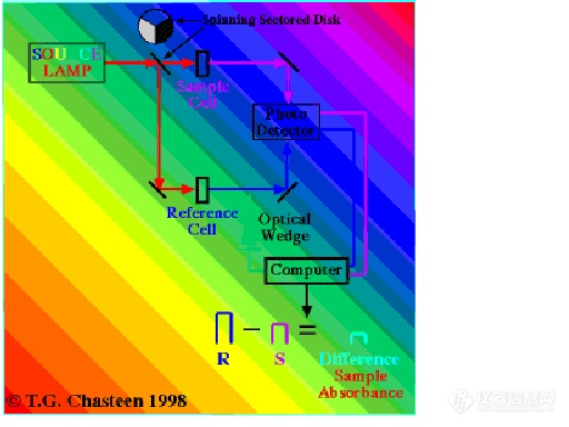
After travelling through either the sample cell or reference cell the light that was not absorbed--by far, most of the beam-- is directed onto the phototransducer or light detector. This component converts the arrival of photons into an electrical signal. By
the way, the light path through the spectrophotometer need not be in a straight line since the light beam can be redirected using mirrors as can be seen here. Sometimes, lenses are also used to collect and collimate the light.
The alternating light signals, from either the reference beam or sample beam generate alternating electrical phototransducer signals. A computer, sampling those signals, can now determine the analyte absorption in two ways. Some instruments merely subtract the sample beam signal's digitized light intensity from that of the reference beam. The difference is a measure of the amount of light absorbed by the analyte.
Since phototransducers-based system are relatively poor at measuring the absolute difference in two different light intensities¨®especially if that difference is large, light absorbances determined in this manner can contain unacceptable amounts of error.
Phototransducer are, however, good at generating signals from light intensities that are close together in intensity; therefore, an alternate means of determining the analyte absorption is used by some instruments:
Some spectrophotometer design uses the digitized reference-minus-sample signal difference to activate a servor motor connected to the computer and a device called an optical wedge. The servor motor slides the optical wedge into the brighter reference beam's path somewhere after the reference cell but before the phototransducer. Remember that since the reference cell does not have any light
absorbing analyte, the light exiting the reference cell will always be brighter than that from the sample cell even if the solvent itself absorbs some at the analyte wavelength since both cuvettes contain solvent. The optical wedge is made of a material that absorbs light so that the more the wedge intersects the reference beam the more of that beam will be absorbed by the wedge and the less will be the difference between the sample and reference signals. The wedge is automatically fed into the reference beam until the reference and sample beam signals are of exactly identical intensity as measured by the phototransducer (remember the
system is good at this). When the signals are equal the amount of wedge needed to produce this 0 signal difference is a measure of the analyte absorption. Since the computer controls the wedge it converts wedge position to an absorbance reading of the analyte.
If Beer's Law holds then absorbance in the linear range will correlate well with concentration and a calibration plot can be constructed and used to determine the concentration of analyte in unknown samples.