主题:【分享】几种气相色谱不常用/常用的检测器原理图(英文)

浏览0 回复22 电梯直达
雨木霖
结帖率:
100%
关注:0 |粉丝:0
新手级: 新兵
The Katharometer Detector
The katharometer was developed in the late 1940s for measuring carbon dioxide in the flue gasses produced from various types of industrial furnaces. A knowledge of the carbon dioxide content allowed the combustion conditions to be changed to improve burning efficiency. With the introduction of gas chromatography, its use as a possible gc detector was explored by Ray . T he sensor is a simple device and is depicted in figure 12.

A filament carrying a current is situated in a tubular cavity through which flows the column eluent. Under equilibrium conditions, the heat generated in the filament is equal to the heat lost and consequently the filament assumes a constant temperature. The heat lost from the filament will depend on both the thermal conductivity of the gas and its specific heat. Both these parameters will change in the presence of a different gas or solute vapor and as a result the temperature of the filament changes, causing a change in potential across the filament. This potential change is amplified and either fed to a suitablerecorder or passed to an appropriate data acquisition system.As the detector filament is in thermal equilibrium with its surroundings and the device actually responds to the heat lost from the filament, the detector is extremely flow and pressure sensitive. Consequently, all katharometer detectors must be carefully thermostatted and must be fitted with reference cells to help compensate for changes in pressure or flow rate.
雨木霖
结帖率:
100%
关注:0 |粉丝:0
新手级: 新兵
The Katharometer Detector

Figure 13. The Off-Line Katharometer Sensor

There are two types of sensor design, the "in-line" sensor where the column eluent actually passes directly over the filament (as shown in figure 12) and the "off-line" cell where the filaments are situated away from the main carrier gas stream and the gases or vapors only reach the sensing element by diffusion.(as shown in figure 13). Due to the high diffusivity of vapors in gases, the diffusion process can be considered as almost instantaneous. The filament wire is usually made from tungsten or platinum as both metals have high temperature coefficients of resistance and at the same time are relatively inert. The column and reference filaments are situated in the arms of a Wheatstone Bridge and a suitable current is passed through the filaments to heat them significantly above ambient temperature. To ensure temperature stability, the sensors and their conduits are installed in a high thermal conductivity metal block which is thermostatted by means of a separate oven. The performance of the in-line sensor is almost identical to that of the off-line sensor.

For maximum sensitivity hydrogen or helium is used as the carrier gas. The katharometer sensitivity is only about 10-6 g/ml (probably the least sensitive of all gc detectors) and has a linear dynamic range of about 500 (the response index being between 0.98 and 1.02).

Figure 14.  The Separation of the Compounds of Hydrogen, Deuterium and Tritium

Despite its sensitivity shortcomings the katharometer can be used in most gc analyses that utilize packed columns and where there is no limitation in sample availability. The device is simple, reliable, rugged and relatively inexpensive. An example of the use of a katharometer to monitor the separation of various compounds of hydrogen, deuterium and tritium, employinggas solid chromatography is shown in figure 14. The stationary phase was activated alumina [treated with Fe(OH)2], and the column was 3 m long and 4 mm I.D. The carrier gas was neon, the flow rate 200 ml/min (at atmospheric pressure) and the column temperature was -196oC.
雨木霖
结帖率:
100%
关注:0 |粉丝:0
新手级: 新兵
The Flame Ionization detector
A detector is considered to be composed of a sensor and associated electronics and it is the sensor unit that is commonly referred to as the FID. A diagram of the FID sensor is shown in figure 16. The body and the cylindrical electrode are usually made of stainless steel and stainless steel fittings connect the detector to the appropriate gas supplies. The jet and the electrodes are insulated from the main body of the sensor with appropriate high temperature insulators. Care must be taken in selecting these insulators as many glasses (with the exception of fused quartz) and some ceramic materials become conducting at high temperatures (200-300oC) .

The use of high voltages in conjunction with the very small ionic currents require that all connections to the jet or electrode must be well insulated and electrically screened. In addition, the screening and insulating materials must be stable at the elevated temperature of the detector oven. In order to accommodate the high temperatures that exist at the jet-tip, the jet is usually constructed of a metal that is not easily oxidized such as stainless steel, platinum or platinum/rhodium.
雨木霖
结帖率:
100%
关注:0 |粉丝:0
新手级: 新兵
The Nitrogen Phosphorus Detector (NPD,大家都知道)
The nitrogen phosphorus detector (NPD) (sometimes called the thermionic detector) is a very sensitive, specific detector the design of which, is based on the FID. Physically the sensor appears to be very similar to the FID but, in fact, operates on an entirely different principle. A diagram of an NPD detector is shown in figure 22.

The NPD sensor differs from that of the FID by a rubidium or cesium chloride bead contained inside a heater coil situated close to the hydrogen jet. The bead is situated above a jet and heated by a  coil, over which the nitrogen carrier gas mixed with hydrogen passes. If the detector is to respond to both nitrogen and phosphorus, then the hydrogen flow should be minimal so that the gas does not ignite at the jet. If the detector is to respond to phosphorus, only, however, a large flow of hydrogen can be used and the mixture burnt at the jet. The heated alkali bead emits electrons by thermionic emission which are collected at the anode and provides background current through the electrode system. When a solute that contains nitrogen or phosphorusiseluted, thepartiallycombustednitrogenandphosphorusmaterials are adsorbed on the surface of the bead.

The adsorbed material reduces the work function of the surface and, thus, electron emission is increased and the current collected at the anode rises. The NPD has a very high sensitivity, i.e., about an order of magnitude less than that of the electron capture detector (ca.10-12 g/ml for phosphorus and 10-11 g/ml for nitrogen).
雨木霖
结帖率:
100%
关注:0 |粉丝:0
新手级: 新兵
The Electron Capture Detector(ECD,大家也都知道)
Lovelock's work on ionization detectors culminated in the invention of the electron capture detector.  However, the electron capture detector operates on an entirely different principle from that of the argon detector. A low energy b-ray source is used in the sensor to produce electrons and ions. The first source to be used was tritium absorbed into a silver foil but, due to its relative instability at high temperatures, this was quickly replaced by the far more thermally stable 63Ni source.
雨木霖
结帖率:
100%
关注:0 |粉丝:0
新手级: 新兵
这资料用途有限。
而且全英文的阅读价值不高。
我只是看到个这样的资料,就转来了。
yifan1117
结帖率:
100%
关注:0 |粉丝:0
新手级: 新兵
zhw19811005
结帖率:
100%
关注:0 |粉丝:0
新手级: 新兵
不错的分享。英文水平比较差,看得有点累,不太习惯
qqqid
结帖率:
100%
关注:0 |粉丝:0
新手级: 新兵
xiaowang268
结帖率:
100%
关注:0 |粉丝:0
新手级: 新兵
原文由 雨木霖(mickeylin) 发表:
The Discharge Detector(放电检测器?还是叫流量检测器?)
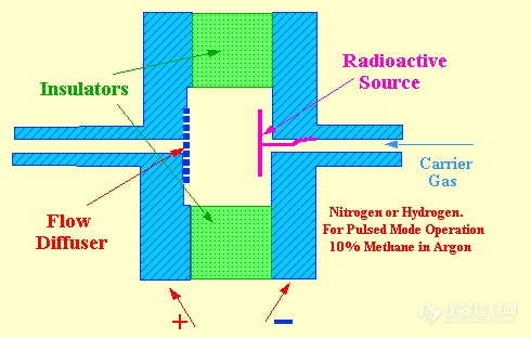
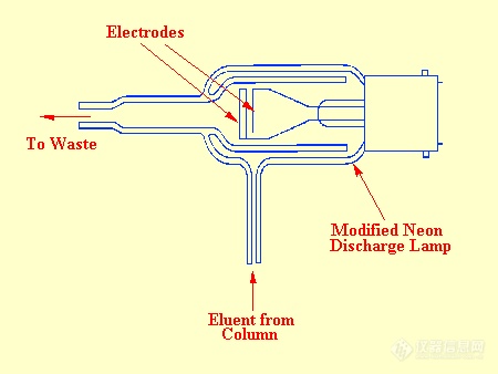
About the same time that Ryce and Bryce were developing the thermionic ionization detector, Harley and Pretorious and  (independently) Pitkethly and his co-workers were developing the discharge detector. By applying the appropriate potential, a discharge can be maintained between two electrodes situated in a gas providing the pressure is maintained between 0.1–10 mm of mercury. After the discharge has been initiated, the electrode potential can be reduced and the discharge will still continue. Under stable discharge, the electrode potential remains constant and independent of the gas pressure and the electrode current.The electrode potential, however, depends strongly on the composition of the gas. It follows, that the system could function as a gc detector. Pitkethly modified a small domestic neon lamp for this purpose and a diagram of his sensor is shown in figure 48.The lamp was operated at about 3 mm of mercury pressure with a current of 1.5. Under these conditions the potential across the electrodes was 220 V. Pitkethly reported that a concentration of 10-6 g/l gave an electrode voltage change of 0.3 V.

The noise level was reported to be about 10 mV thus at a signal–to–noise level of 2 the minimum detectable concentration would be about 3 x 10-11g/ml. This sensitivity is comparable to that of the FID and the argon ionization detector. The detector was claimed to be moderately linear with a linear dynamic range of three orders of magnitude but values for the response index were not reported. It was not apparent whether the associated electronics contained non linear signal modifying circuitry or not. Unfortunately, there were several disadvantages to this detector. One disadvantage was the erosion of the electrodes due to "spluttering" In addition, the electrodes were contaminated by sample decomposition and it was essential that it was used with a well–controlled vacuum system.


放电检测器?没听说过啊
猜你喜欢最新推荐热门推荐更多推荐
品牌合作伙伴