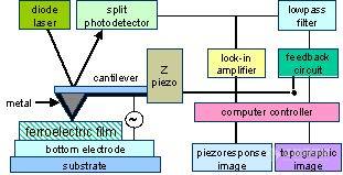
The basic idea of Piezoresponse Force Microscopy (PFM) is to effect locally the piezoelectric sample surface by the electric field and to analyse resulting displacements of the sample surface[1].
The PFM technique is based on the converse piezoelectric effect, which is a linear coupling between the electrical and mechanical properties of a material. Since all ferroelectrics exhibit piezoelectricity, an electric field applied to a ferroelectric sample results in changes of its dimensions.
To detect the polarization orientation the AFM tip is used as a top electrode, which is moved over the sample surface. In the Intro1 animation one can see the reaction of out-of-plane and in-plane domains in the ferroelectric film on the voltage applied to the scanning tip in Contact Constant Force Mode. The electric field generated in the sample causes the domains with the polarization parallel to the field to extend and the domains with opposite polarization to contract.
If the polarization vector is perpendicular to the electric field, there is no piezoelectric deformation along the field direction, but a shear strain appears in the ferroelectric, leading to displacements of the sample surface parallel to itself, along the polarization direction.
The AFM probe tip moving according to the surface displacement causes cantilever normal or torsion (because of friction) deflections. Direction of the deflection depends on the mutual orientations of the electric field and domain polarization. Correspondingly in the case of the AC electric field phase lag between the electric field and cantilever deflections will depend on the their mutual orientations. In general case by analyzing the amplitudes and phases of the normal and torsion cantilever vibrations one can reconstruct the sample domain structure.
![]()

