获得0积分,您同时完成了每日任务,有额外的积分奖励,请前往APP领取
立即前往
原文由 perpetualcat68(perpetualcat68) 发表:
这个模式也还是个近似,考虑到了point spread function, defocus, background(含TDS), 但样品厚度的波动不在里面(通常对3种以下元素构成的样品可以做simulation.).还有STEM的"flyback error". 这两个因素还不太好用高斯函数来近似概括.
样品FIB加工后再用Gentel Ion Miller处理会好很多.
本来是对单个边缘近似描述的,比较成型了(很多测量都在用, x-ray等也在用), 后来我试着把它扩展到双边,最后干脆对整个扫描范围. 所用参数的物理含义并未改变.
如果将这个模式对映到diffusion就更有意思了.HRSTEM 的"Z-contrast"可以"转译"成元素分布,diffusion(Fick's law)本身也含有error function. 这方面还要多次进行EDX测量来评估.
这方面有很多相关的文献,困难点在于如何对4或5种以上元素组成的样品进行模拟. 对3种元素的分布描述已很成熟了.TEM/STEM的测量脱离不了reference和simulation以及和其他方法的比较(比如synchrotron radiation在HRXRD的使用).很多地方都在尝试中,太麻烦.
原文由 tevis(tevis) 发表:
I didn't know the error function of Fick's law until just now. Can you post a (good) paper instead of wiki? Wiki is helpful but usually cannot be used as a reference. I am wondering how this erfc function is proven to be right (and useful) for diffusion in solid materials. I briefly googled the erfc function: it is a integral from x to infinite. How do you tweak this function (also your I(x)) for your modulated thin film with limited size?
Back to your original question, my understanding is that you try to define the edges with a resolution better than 0.02 nm. It is smaller than the atomic spacing. Your images don't have this resolution.
原文由 perpetualcat68(perpetualcat68) 发表:原文由 tevis(tevis) 发表:
I didn't know the error function of Fick's law until just now. Can you post a (good) paper instead of wiki? Wiki is helpful but usually cannot be used as a reference. I am wondering how this erfc function is proven to be right (and useful) for diffusion in solid materials. I briefly googled the erfc function: it is a integral from x to infinite. How do you tweak this function (also your I(x)) for your modulated thin film with limited size?
Back to your original question, my understanding is that you try to define the edges with a resolution better than 0.02 nm. It is smaller than the atomic spacing. Your images don't have this resolution.
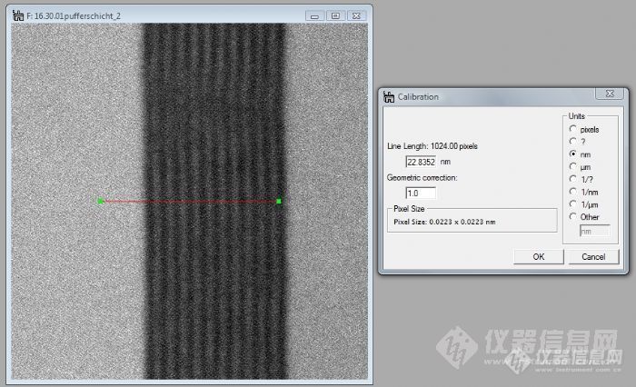
The pixel size of the HRSTEM image is 0.0223 x 0.0223nm.
Do you understand edge detection with sub-pixel accuracy based on approximation of edge
with erf function?
By the way, error function is not only an integral from x to infinite.
原文由 蓝莓口香糖(drizzlemiao) 发表:
误差函数其实就是高斯函数和台阶函数的卷积。如果假设样品的成分相对于电子束斑足够小,就可以用台阶函数近似势场分布。然后用高斯函数近似束斑强度分布,图像强度就是误差函数。
扩散理论里面的误差函数导出是完全另一回事。假设起始时刻成分偏聚是个脉冲函数,发生扩散后,成分分布就是个高斯函数。对于一端偏聚的情况,偏聚部分可以看作是一系列脉冲函数的集合,因此某时刻某个位置的浓度就是这一系列脉冲偏聚在该时刻该位置浓度的加和,这其实就是高斯分布和台阶函数的卷积过程。所以也会出现一个误差函数。